JAIVIC MEDIUM VOLTAGE SHUNT POWER FACTOR IMPROVEMENT CAPACITORS SERIES REACTOR AND PROTECTION ACCESSORIES

JAIVIC Capacitors are designed and manufactured with the latest technology by ‘Jaivic Electromech Engg. Pvt. Ltd.’ At their most modern plant at Nasik. The Organisation is backed by a team of people having years of experience & expertise in the field. Hundred percent capacitors are thoroughly tested at every stage of manufacturing and all the routine and type tests are rigorously carried out as per IS: 13925 with latest version. This ensures excellent trouble-free service under most critical conditions of operation.

`JAIVIC’ H.T. Capacitors are used in various applications such as, in distribution systems in mines, Electricity boards, in Industries, for testing application etc. These are used across big motors for lift irrigation schemes, water supply etc. For Power Factor Improvement.

CONSTRUCTION & DESIGN OF H.T. SHUNT CAPACITORS

Each Basic element is wound in clean & dust free atmosphere on fully automatic HT Winding machine with the help of Electrical grade Imported biaxially oriented polypropylene film and a high purity soft annealed Aluminum foil.

The Winding of element is flat type. The Elements connected in parallel are formed in series groups to meet the voltage requirement.

The complete stack assembly is insulated with high grade electrical insulating material to get the desired insulation level. And total stack inserted in CRCA/SS container. For terminals of capacitor using high class glazed porcelain bushings.

The capacitor are dried under high vacuum and impregnated by synthetic liquid (PXE) under accurately controlled conditions.

Capacitors are designed to have very low loss generally less than 0.2 watts per kvar.

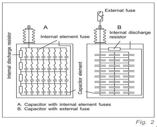
Every individual capacitor element is protected by fuse. In case of element failure during abnormal condition, only one element is disconnected, after disconnection of faulty element, the capacitor unit restores the normal operation within milliseconds with a slightly reduced output. Due to internal fuse the risk of case bursting is considerably reduced.

Specification:

  • Non Self Healing Type, IS:13925

Range:

  • Output: Upto 300 kvar of single unit
  • Voltage: 1.1kv, 3.3kv, 3.6kv, 6.35kv, 7.2kv, 50/60Hz
  • Phases: Single Ph & Three phase

Salient Features:

  • All Polypropylene (APP) film Foil Design
  • Internal Element Fuse Protection
  • Non PCB PXE Oil
  • Highest Inrush current with standing capacity
  • Suitable for Harmonic loads
  • Compact construction
  • Custom Designs Available
  • Also Special Purpose Capacitors
img/ht_shunt/jaivic-ht-shunt-capacitors-nashik-india.jpg

Design details of HT-APP

img/ht_shunt/HT-shunt-capacitors-nashik-india.jpg

PRODUCT RANGE

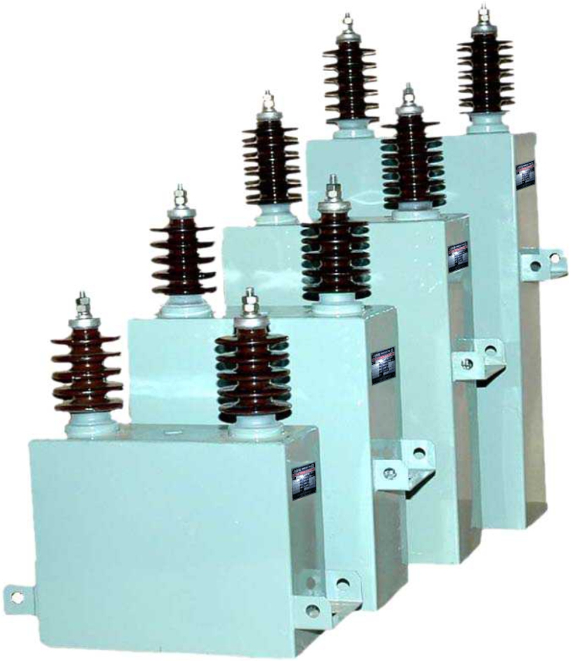
Standard Capacitors are Available: in 1.1, 3.3, 6.6, & 11 kV voltage class and in Output rating of 50Kvar to 500 Kvar in single unit, Different ratings are available on request.

ELECTRICAL TESTING

Routine Electrical tests are carried out as per IS: 13925:1998, Type test are carried out as per customers requirements.

TECHNICAL PARTICULARS OF HT APP SHUNT CAPACITOR

#
PARTICULARS
SPECIFICATIONS
01
Make & Type
“Jaivic “ make, Indoor / outdoor type
02
Type Of Dielectric
Imported Biaxially Oriented Polypropylene film ( BOPP)
03
Type Of electrode
High Purity (99.9%) soft annealed 5 micron Aluminium Foil
04
Type Of Impregnant
NPCB, PXE Oil
05
Designing Of Capacitor
Designing with very less voltage stress
06
Protection system
HT HRC Fuses of suitable capacity
07
Internal Protection
Internal Element Fuse Design
08
Energy consumption, Watts/kVAr
0.2 Watts/kVAr ( Maximum )
09
Reference Standards
IS:13925-1998 With it’s latest amendment,IEC-60871
10
Rated capacitor unit
From 50 kvar to 500 Kvar
11
Normal system voltage
1.1,3.3,6.6,up to 11 KV system voltage
12
Rated frequency
50 HZ
13
Rated current
As per requirement
14
No. of phases
1 Or 3 Phases
15
No. of terminals
2 or 3 Terminals
16
No. of bushings
2 or 3 Bushings
17
Type of Bushing Terminal
High gloss Porcelain bushing
18
Connection of capacitor unit
Series-parallel connection of capacitor unit
19
Maximum permissible over voltage
110% of rated voltage
20
Maximum permissible current
130% of rated current
21
Residual voltage
50V or less within 10 minutes
22
Maximum time interval required between de-energisation & re-energisation of the Bank
5 minutes
23
Discharge device
Internally fitted discharge resistors
24
Limiting ambient Temperature
50 Deg. C. As per IS
25
Temperature Rise
10 o C above ambient.
26
Type of container
M.S. / S.S.
27
Thickness of container
16 Swg / 18Swg
28
Surface treatment
Zinc Phosphate
29
Paint Finish
One coat Epoxy Primer and final coat Silver grey Epoxy paint
30
Voltage Test For capacitor Unit Between Terminal
Rated voltage X 4.3 times D.C. Voltage for 10 sec.
31
Between Terminal & Body
As per IS 13925
32
Impulse Withstand Voltage
As per IS 13925

33) FEATURES:

  • Extended foil design.
  • Design with several layer of BOPP film + Aluminum Foil construction.
  • High dielectric strength.
  • Available with Internal / External fuses.
  • Longer life & high reliability.
  • Low energy consumption.
  • Available in M.S. / S.S. Container.
  • Suitable for indoor & outdoor application.
  • Design varied based on the type of system.
  • Available with cubical of Isolator, Reactor, & HRC Fuses assly.
  • Suitable for the most arduous system condition.
  • Banking: Star, Delta, Double Star.

34) Misc. /others:

  • Suitable and appropriately rated isolatory i.e. control device shall provide and erected by the contract under this item. Moreover, mounting stand shall be fabricated from M.S. Iron angle after getting the approval for design from competent authority.
  • Entire unit including capacitor stand control device, protecting fuses, cables, etc. shall stand for one year guarantee from the date of final commissioning.
  • Unit shall be tested for routine test as per relevant I.S.S. at the manufacturers shop (before dispatch) in presence of buyer’s representative. Similarly, same will also be tested at the site of the work for their faultless performance before connecting.
  • Complete unit shall be enclosed in sheet steel cubical duly painted and marked with name plate details such as Sr. No. Make, Brand, Type etc.

35) ACCESSORIES & PROTECTION DEVICES

  • The kVAr rating of capacitor, which is connected across the motor permanently, should be less than the magnetizing kVAr of motor.
  • When capacitors are connected permanently across the motor, the total line current drawn by the motor is reduced. As such the overload protection relay in starter of the motor requires resting.
  • HRC Fuses: For proper protection to Capacitors, current limiting high voltage HRC Fuse links are recommended for external use along with Capacitors.
  • Series Reactors: Standard ratings are 1% and 6% of kVAr of Capacitors.

0.2% reactor can be used to limit switching surge current parallel operation of Capacitor banks, Reactors are manufactured as per ISS 5553 Part II.

Detailed dimensional drawing available on request.

If you need any further technical information, Please write to us and we would be willing to provide the same.